Residential Recirculation: Visual Guides for Your Hot Water System
By Brian on October 1, 2025
Why Instant Hot Water Matters
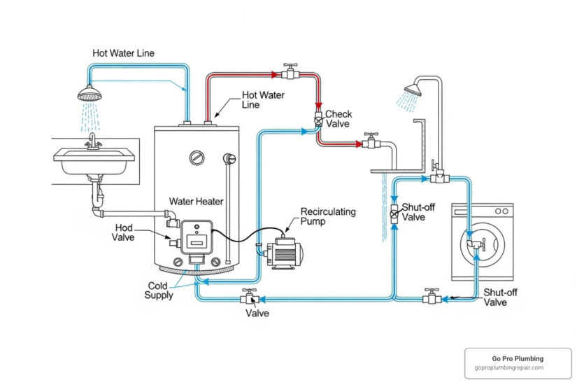
A hot water recirculating pump installation diagram is a visual guide showing how to connect a pump system to eliminate the wait for hot water. It clarifies where each component goes and how they work together to provide instant hot water throughout your home.
Key Installation Diagram Elements:
- Recirculation pump: Installed at the water heater’s hot outlet.
- Sensor valve: Placed under the furthest sink (for retrofit systems).
- Check valve: Prevents backflow in return lines.
- Timer/Aquastat: Controls pump operation.
- Hot water supply line: Carries heated water to fixtures.
- Return line: Brings cooled water back to the heater.
The average household wastes over 3,000 gallons of water annually just waiting for hot water. Recirculation systems solve this by keeping heated water moving through your pipes, so it arrives instantly at the faucet. This eliminates waste and can lower water heating costs.
Installation diagrams show two main system types. Full recirculation systems use a dedicated return pipe, ideal for new construction. Comfort systems are retrofitted into existing homes by using the cold water line as a return path.
Understanding these diagrams is key to choosing the right system and ensuring proper installation for maximum efficiency.

Understanding Your Hot Water Recirculating Pump Installation Diagram
This section breaks down the visual schematics, helping you identify key parts and understand how they connect, regardless of your specific system type.
Key Components in a Hot Water Recirculating Pump Installation Diagram
When you look at a hot water recirculating pump installation diagram, you’ll notice several recurring components. Each plays a vital role in ensuring hot water is delivered quickly and efficiently to your fixtures. Understanding these parts is the first step to a successful installation.

Here’s a breakdown of the key players:
- Recirculation Pump: The heart of the system, this electric pump circulates water, moving cooled water from the hot water lines back to the water heater. This ensures a continuous loop of hot water is available near your faucets.
- Check Valve: This crucial component ensures one-way flow. It prevents cooler water from mixing into the hot water supply or hot water from entering the cold water line in retrofit systems.
- Sensor Valve (Bypass Valve): Used in retrofit (“comfort”) systems, this valve is installed under the sink furthest from the water heater. It connects the hot and cold lines, opening to let cool water in the hot line flow into the cold line to create a return path. It closes once hot water arrives.
- Timer or Aquastat: These controls dictate when the pump operates. A Timer lets you run the pump only during peak usage times (e.g., mornings and evenings) to save energy. An Aquastat senses water temperature, activating the pump when it drops below a set point (e.g., 95°F) and shutting it off when hot, ensuring readiness without constant pumping.
- Isolation Valves: Installed on both sides of the pump, these shut-off valves allow you to isolate it for service or replacement without draining your entire plumbing system.
- Hot and Cold Water Lines: Your existing plumbing. The hot line carries heated water from the water heater, while the cold line brings in fresh water and, in retrofit systems, serves as the return path.
For more in-depth information on how these components fit into system design, you can refer to our guide on More info about system design.
Diagram 1: System with a Dedicated Return Line
The “full recirculation” system is often considered the gold standard. A hot water recirculating pump installation diagram for this setup shows a separate pipe running from the furthest fixture back to the water heater.

This system uses a dedicated pipe to return cooled water to the heater, creating a closed loop. The pump, usually near the water heater, pushes hot water through the supply lines. The cooled water is then sent back via the return line to be reheated, eliminating waste.
Key characteristics of a dedicated return line system:
- Optimal Efficiency: Constant circulation in a closed loop means minimal temperature drop and instant hot water, significantly reducing water waste.
- Common in New Construction: Installing a dedicated return line is easiest during initial construction or a major renovation.
- Pump Placement: The pump is almost always located at the water heater, pushing water into the hot supply lines.
- No Mixing with Cold Water: There is no interaction with the cold water line, ensuring your cold water stays cold.
This system is ideal for homes with long pipe runs. For comprehensive piping diagrams, you can check out Technical Bulletins – Piping Diagrams for Hot Water Recirculating Loops | A. O. Smith. For more details, explore our resource on More info about dedicated return lines.
Diagram 2: System Using the Cold Water Line (Retrofit)
For existing homes, a “comfort” or retrofit system is a popular choice. A hot water recirculating pump installation diagram for this type shows a pump at the water heater and a sensor valve under the furthest sink.

This system cleverly uses your existing cold water plumbing as a temporary return path.
- No Dedicated Return Pipe Needed: It uses the existing cold water line, avoiding the need to install a new pipe.
- Under-Sink Sensor Valve: A sensor valve under the furthest sink connects the hot and cold lines. When the pump runs, it pushes cooled water from the hot line into the cold line, which carries it back to the water heater.
- Temporary Warming of Cold Water: A minor trade-off is that the cold water line may become temporarily warm near the sensor valve. This effect dissipates quickly when cold water is drawn.
This setup is designed for easy retrofitting into existing plumbing. To understand the mechanics, dig into How a Hot Water Recirculating System Works.
Diagram 3: System with a Tankless Water Heater
Integrating a recirculation pump with a tankless water heater requires specific considerations. A hot water recirculating pump installation diagram for this setup will highlight unique connection points.

Here’s what makes this integration special:
- Tankless Compatibility: Many modern tankless heaters are designed for recirculation, with built-in logic or ports to prevent short-cycling (frequent on/off cycles) from the pump’s flow.
- Flow Rate Requirements: Pumps help meet the minimum flow rate (e.g., 0.5 GPM) required to activate tankless heaters, ensuring instant hot water even at low-flow fixtures.
- Specific Connection Points: The diagram will show the pump on the hot outlet, with the return line connected to the cold inlet or a dedicated recirculation port. An expansion tank is often needed.
- System Sizing: The pump must be sized correctly for the system. Some models can handle pipe lengths of 400 ft or more, making them suitable for larger homes.
Integrating a pump with a tankless heater offers on-demand heating with the convenience of instant hot water. For a typical diagram, see On-Demand Heater With Recirculation – Bradley Corporation.
Pre-Installation Checklist: Sizing, Tools, and Safety
Before you begin, proper preparation is crucial for a smooth and safe installation. This involves selecting the right size pump, gathering your tools, and understanding the safety protocols.
Sizing Your Recirculation Pump
Your hot water recirculating pump installation diagram shows the layout, but you must choose the right size pump for your home. The most important factor is total pipe length, including all fittings, twists, and turns. Pumps are rated for specific equivalent pipe lengths (e.g., 250 ft, 400 ft, or more).
Pump sizing depends on friction loss, not the number of floors in your home. Pipe diameter is also crucial, as smaller pipes create more resistance. Your water heater type matters, too; tankless heaters often need a minimum flow rate (e.g., 0.5 GPM) that the pump must provide.
Factors to consider when sizing a pump:
- Total pipe length including all fittings and turns
- Pipe diameter throughout your hot water system
- Water heater type and minimum flow requirements
Tools and Materials
Gathering your tools and materials beforehand will prevent delays.
Necessary tools:
- Pipe wrenches
- Tube cutter (for copper pipe)
- Pliers
- Screwdriver
- Bucket and rags
- Drill with bits (e.g., 3/4-inch spade bit for control buttons)
- Tape measure
Typical materials:
- Pump kit (pump, sensor valve, fittings)
- Flexible supply lines
- Teflon tape
- Additional fittings or adapters as needed
Electrical and Safety Precautions
Your hot water recirculating pump installation diagram will show electrical connections, but safety is paramount.
Most pumps use a standard 115V grounded outlet. Ensure the outlet is properly grounded and keep the power cord away from hot exhaust pipes. For any hard-wired connections, use wire rated for at least 221°F with copper conductors only.
Before starting:
- Shut off the power to your water heater and the work area. For gas heaters, turn off the gas supply.
- Shut off the main water supply to the house or at least to the water heater.
- Open a hot water faucet to relieve pressure and drain the lines.
Safety Tip: Hot water can cause severe burns. Let the water in the pipes cool to below 100°F before starting work.
Always check and follow local plumbing and electrical codes, as they take precedence over general instructions. If you’re unsure about any step, especially the electrical work, call a professional. As This Old House emphasizes, following proper safety guidelines is crucial.
A Visual Guide to Installation: Step-by-Step
Follow these general steps, using your specific hot water recirculating pump installation diagram as your primary guide for a successful setup. While diagrams vary, the core principles remain the same.
Step 1: Pump Installation at the Water Heater
Your hot water recirculating pump installation diagram will show the pump connected to the hot water outlet pipe of your water heater.
- Shut off power and water to the system as described in the safety precautions.
- Drain the hot water line by opening a faucet to relieve pressure.
- Disconnect the existing hot water line from the heater’s outlet and connect the pump. Use Teflon tape or pipe dope on threaded connections for a watertight seal.
- Ensure the flow direction arrow is correct. The arrow on the pump must point away from the water heater and toward your home’s hot water supply lines.
- Position the motor horizontally for longevity, unless the instructions permit vertical installation. Avoid installing the pump outdoors or in low spots where sediment can collect.
For more detailed information on installing these systems, refer to our guide on how to install hot water recirculating system.
Step 2: Sensor Valve Installation (for Retrofit Systems)
If your diagram shows a retrofit system, this step uses the cold water line as a return path.
- Install the sensor valve at your furthest fixture, typically the sink farthest from the water heater.
- Shut off the angle stops (the small valves under the sink) for both hot and cold water.
- Connect the sensor valve. Disconnect the faucet’s supply lines. Then, connect the sensor valve to the hot and cold angle stops and to the faucet’s hot water inlet, using the flexible lines from your kit.
- Do not use Teflon tape on the sensor valve threads. These valves use O-rings or gaskets to seal, and tape can cause leaks.
- Securely mount the valve under the sink to prevent strain on the pipes.
Step 3: Final Connections and System Start-Up
With the main components in place, it’s time to bring your system to life.
- Reconnect all supply lines and double-check that all connections are snug.
- Slowly turn the main water supply back on. Watch and listen for any leaks. If you find one, shut the water off and re-tighten the connection.
- Visually inspect all new connections for drips.
- Purge air from the lines. This is crucial for proper operation. Open hot water faucets throughout your home, starting with the one closest to the water heater. Let them run until the stream is steady. Air in the lines can cause pump noise and reduce efficiency.
- Plug the pump into a properly grounded electrical outlet, ensuring the cord is routed safely.
- Test your system. Activate the pump using its controls (timer or button). After a few minutes, test the hot water at various faucets. It should arrive much faster. If the pump is noisy, try bleeding more air from the system.
Optimizing and Maintaining Your System
An installed system is just the beginning. Proper settings and maintenance will ensure your pump runs efficiently for years.
Setting Timers and Controls
Fine-tuning the controls is key to balancing convenience and cost savings.
- Programming for peak use: Set your timer to run the pump only during periods of high hot water demand, such as mornings and evenings. This avoids the energy waste of circulating water when it’s not needed.
- Aquastat temperature settings: If your system has an aquastat, set it to maintain water between 95°F and 110°F. This reduces energy use while still providing comfortable hot water. Keeping your water heater below 140°F also helps prevent scale buildup.
- On-demand button use: For maximum energy savings, use an on-demand button to activate the pump manually only when you need instant hot water.
A well-programmed system can be more efficient than traditional plumbing by eliminating the energy wasted heating water that cools in the pipes. For more on efficiency, see our guide on Are Hot Water Recirculation Systems Efficient?.
Troubleshooting Common Issues
Even with a perfect hot water recirculating pump installation diagram and installation, issues can arise. Most have simple solutions.
- Pump is noisy: This is often caused by air trapped in the lines. Bleed the system by opening faucets, starting with the one closest to the heater, until the water stream is steady.
- No hot water delivery: First, check that the pump has power. Next, verify that all isolation valves are open and there are no blockages. A stuck internal check valve could also be the issue.
- Cold water is warm: This is normal for retrofit systems near the sensor valve. Run the cold water briefly to cool it down. If the problem is persistent or widespread, inspect your check valves.
- Temperature inconsistencies: This may point to incorrect aquastat settings or a failing sensor valve. Check your settings and test the valve; replace it if it’s faulty.
For comprehensive troubleshooting, visit our resource on More info on system problems.
Long-Term Maintenance and Water Quality
Your system’s longevity depends on water quality and regular maintenance.
- Hard water impact: Hard water causes mineral scale buildup, reducing efficiency and potentially causing failure. If you have hard water, consider installing a water softener.
- Scale buildup prevention: Keep your water heater temperature below 140°F. Flush the system annually to remove accumulated sediment.
- Regular leak inspections: Routinely check all connections around the pump and sensor valve for moisture or mineral deposits (white or green stains).
- Pipe insulation: Insulating your hot water lines reduces heat loss, making your system more efficient and reducing the pump’s workload. It also helps prevent burst pipes in the winter.
- Annual professional maintenance: A qualified plumber can check performance, test connections, and clean components to prevent costly repairs and extend your system’s lifespan.